Dataset
Click here to download the dataset.
The dataset contains \(N=500\) measurements of the humanoid robot Agile Justin. Each data point consists of a tuple \( (q, y) \) with the commanded joint configuration \(q\) and the corresponding positions of the left and the right end-effector \(y\). All the joints are in rad and the positions are provided in the frame of the camera system. The measurements were acquired using an external camera system from Vicon, consisting of six 16Mpx cameras mounted on the ceiling, which tracked the two retro-reflective markers on the robot’s hands.
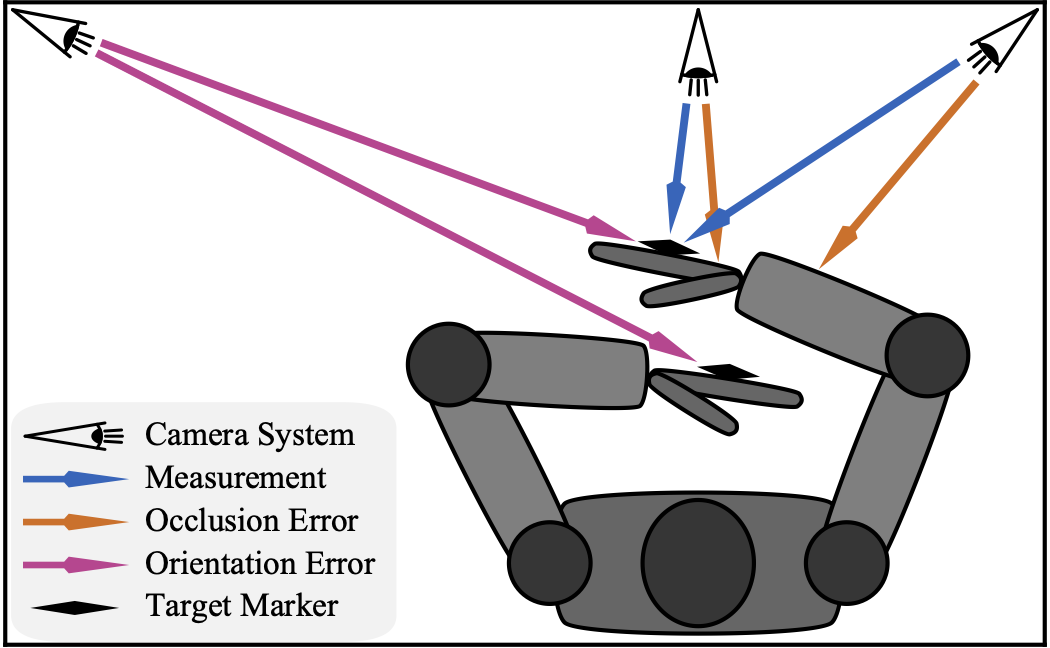 The sketch demonstrates the measurement setup with cameras tracking markers on the end effectors; showcasing the problem of occlusion and suitable orientation of the marker for a given robot configuration.
\[y = h(q, \Theta) = {}^{\mathrm{c}}T_0 \cdot f^*(q, \rho_0, \kappa, \nu)_{\mathrm{r}, \mathrm{l}} \cdot [p_{\mathrm{r}}, p_{\mathrm{l}}]\]
To close the measurement loop we need some additional frames and positions Initial guesses for the base of the robot \({}^{\mathrm{c}}T_0\), and the marker positions on the right \(p_\mathrm{r}\) and left arm \(p_\mathrm{l}\) are:
\[\begin{align} {}^{\mathrm{c}}T_0 = \begin{bmatrix} 0 & -1 & 0 & -2.5 \\\ 1 & 0 & 0 & 2.0 \\\ 0 & 0 & 1 & 0.1 \\\ 0 & 0 & 0 & 1 \end{bmatrix} && p_{\mathrm{r}} = [-0.1, -0.03, 0.1] && p_{\mathrm{l}} = [-0.1, 0.03, 0.05] \end{align}\]